3.1 Circuit Representation
The following diagram shows the practical single phase diode bridge rectifier. It has capacitor at DC stage and the input ac line is represented by a series RL circuit.
Figure 1. Single phase diode rectifier
3.2 Circuit Operation
The circuit diagram is shown in part 3.1. A large filter capacitor is connected on the dc side. The supply is modeled as a voltage source, with inductive impedance. The operation of the rectifier is very simple. During the positive half cycle of source voltage, Vs, D1 and D2 conduct the current and the voltage on the dc side Vd = Vs. During the negative half cycle of Vs, D3 and D4 conduct and Vd= -Vs. So the result is:
Vd (open cct) = |Vs|
3.3 Circuit Representation for Pspice
The following diagram shows the circuit as seen represented by the code for Pspice simulation. The nodes were numbered as shown.
Figure 2. Single Phase diode rectifier with nodes numbered.
3.4 Input File for Simulation
The following code was used to simulate the practical single phase diode bridge rectifier shown above.
Single-Phase, Diode-Bridge Rectifier
VS 1 0 SIN(0 170V 60 0 0 0)
LS 1 2 1mH
RS 2 3 1m
LD 4 5 1uH
RLOAD 5 6 50.0
CD 5 6 1000uF IC=160V
D1 3 4 PDIODE
D3 0 4 PDIODE
D2 6 0 PDIODE
D4 6 3 PDIODE
.MODEL PDIODE D(IS=1E-10 N=1 BV=1200 IBV=10E-3 VJ=0.7)
.TRAN 1m 1000m UIC
.PROBE
.END
3.5 Simulation Results
The following graph shows the rectified output compared with the sinusoidal input.
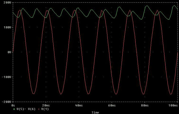
Figure 3. Rectified output [ V(5)- V(6) ] compared with input V(1).
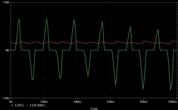
Figure 4. Current in the load resistor I(RLOAD) compared with the current drawn from the source I(RS).
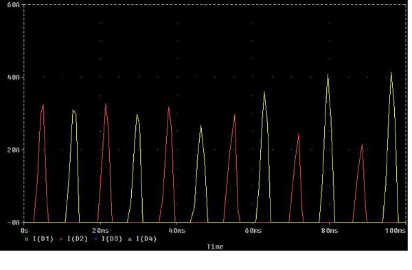
Figure 5. Current drawn by the four diodes.
3.6 Interpretation
In figure 3, it can be seen that the sinusoidal input has been converted to a DC output, although there are some ripples. Here the frequency of the input voltage was 60 Hz, and its rms value was 120V. Hence, the period is 16.67 ms. In each period, it can be seen that there are two ripples, corresponding to the positive and the negative half cycles of the input waveform. The ripples have been improved to a large extent by the capacitor on the dc side. The same analysis can be extended to the current waveforms. Each diode conducts only for half of the cycle of input voltage.
